3D scan and reverse engineer a Garrett turbo
We had the pleasure of scanning a pair of Garrett supercharger blades (G35 and GTX35) for a customer that will be making their own unique supercharger body and blades.
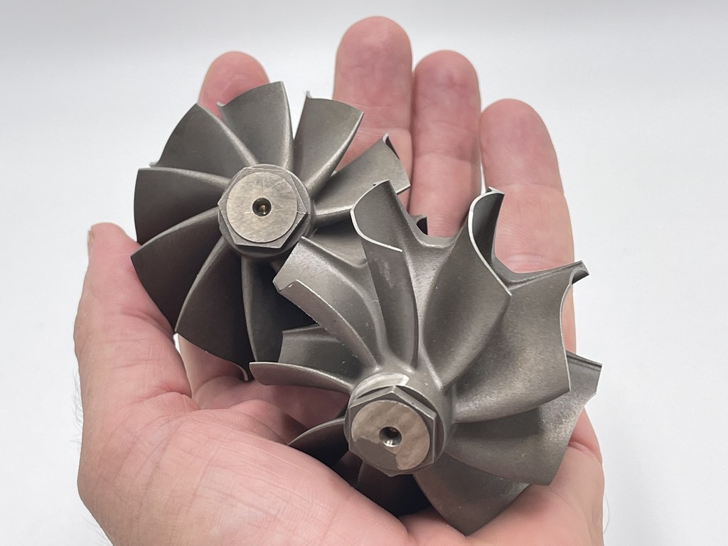
This project was rather interesting due to the level of precision needed for designing something as precise as these turbines spin at 130,000 RPM. At that speed, precision is imperative. We provided the customer with more precise data and designs than the original “as-built” turbine blades that we scanned. How is that possible? When you build anything, errors get into the process. With Garrett turbines, they are a very high precision investment casting. But even with that beautiful casting process, each blade is a little bit different. We used 3D Systems Geomagic DesignX feature called “average meshes” that allow us to take the blade data from all of the blades and average the data together to get a very precise blade design. With this very high-quality data set, there is still a little ‘noise’ in the surface data. We then further processes that data in DesignX and make a perfectly smooth blade.
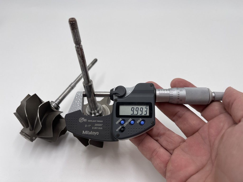
The 3D laser scanning tools we used to scan the blades were a Faro Arm and the Faro LLP laser with a maximum accuracy of 25 microns. We also used Mitutoyo micrometres to work to measure the shafts to +/- 1 micron. We use 3D Systems Geomagic Studio for the scanning process. After we scan, we use 3D Systems Geomagic DesignX to clean, process and align the data. We use DesignX for all the reverse engineering. To finish it off, we use SolidWorks for all the 2D drafting needs.
We are delighted to show some of DesignX’s feature analysis tools that help us with the precision drawings. There are 5 processes we will examine. There are over 25 pictures, below:
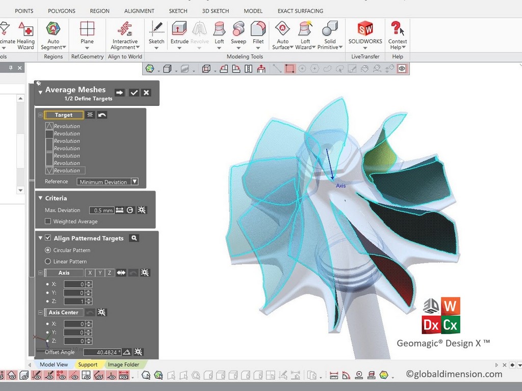
1: Averaging meshes
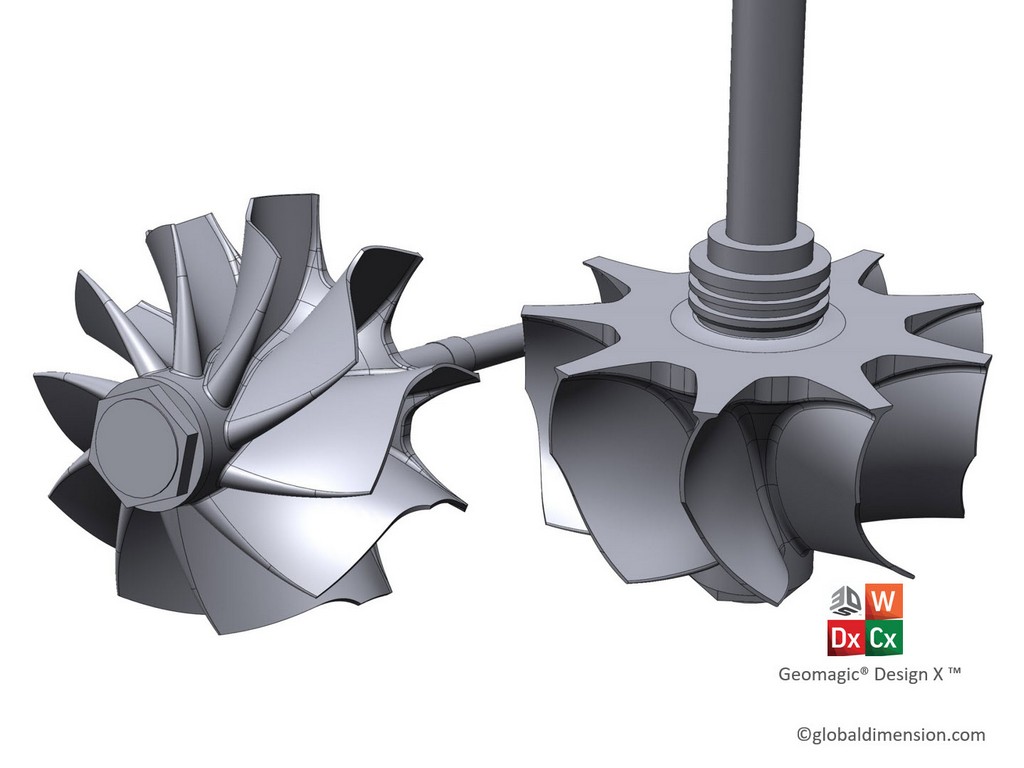
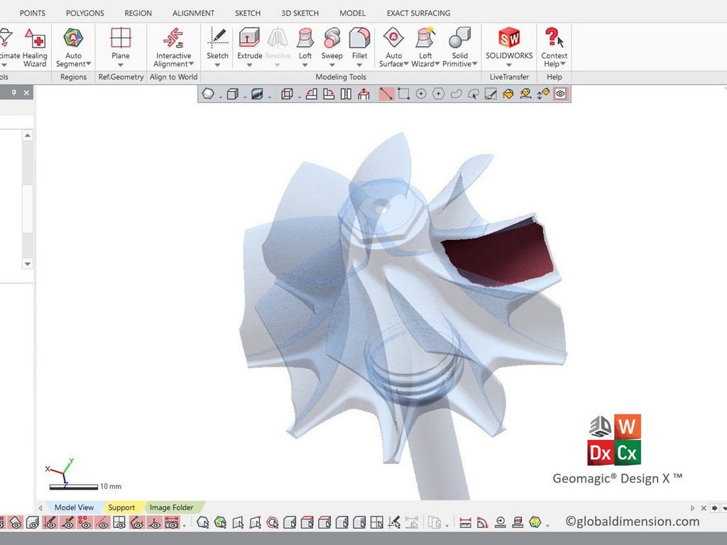
We compare the basic scan data (without combining/averaging the data of all the blades) versus using the more refined ‘average meshes’. We then take this averaged blade data (300,000 polygons per blade x 9 blades) and make a class-A CAD surface as shown in the images with the ‘zebra lines’.
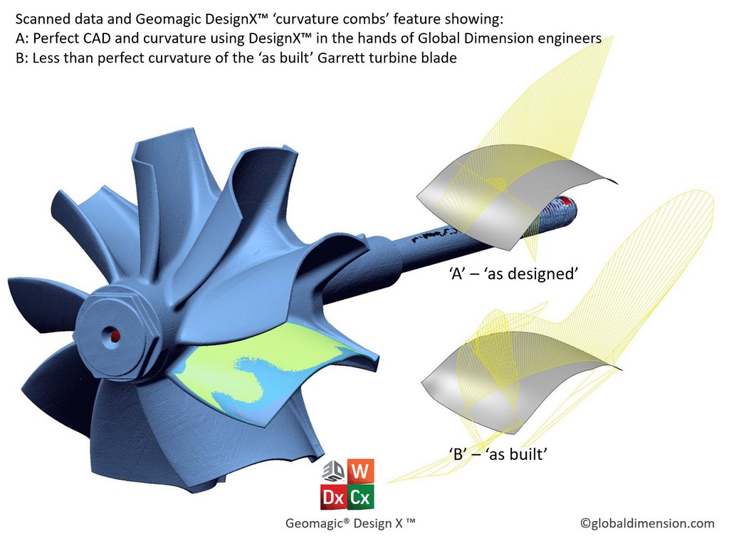
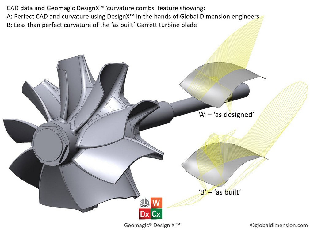
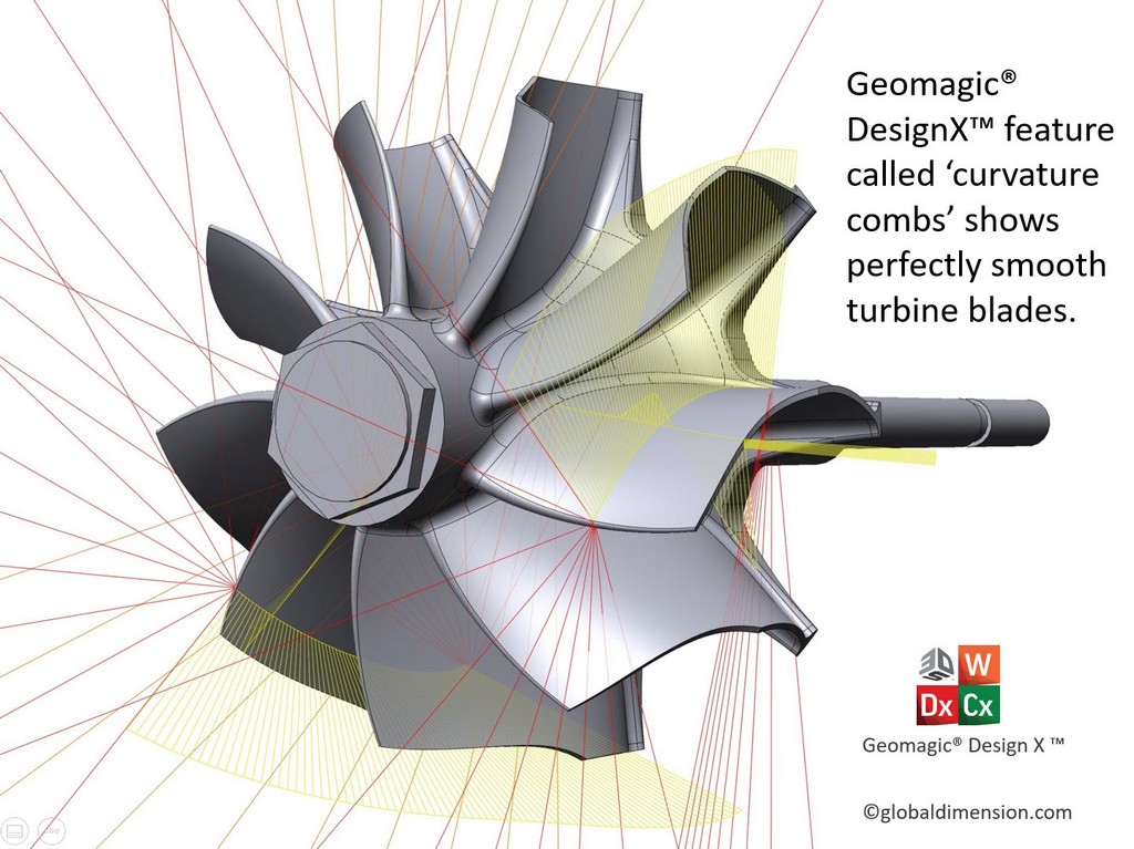
2: Curvature combs
We use also use DesignX’s tool called ‘curvature comb’ that allows us to see how smooth the surface really is. The yellow curve should be a nice-looking uniform curve. If there is any issue with the surface, it will appear as a bump or change in the smooth flow of the curve. You can think about this curve like an amplification of the surface, and if there is even a tiny variation, it shows up in this curve. We show an ‘as built’ curve versus our perfected CAD blade design.
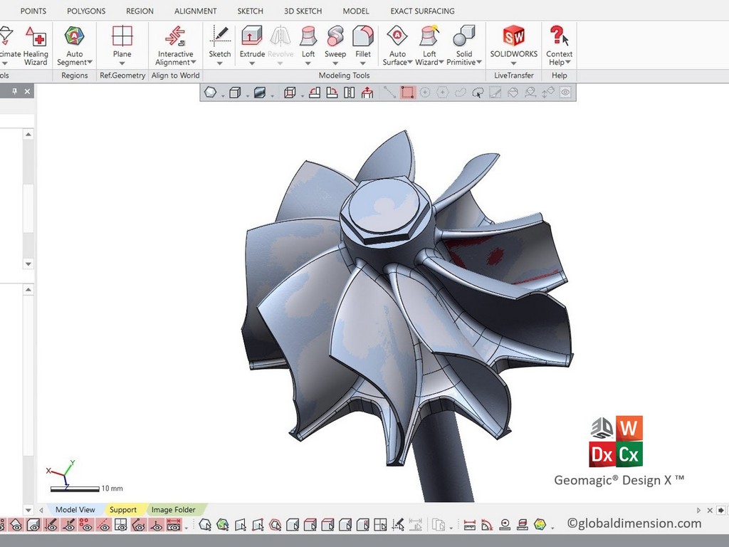
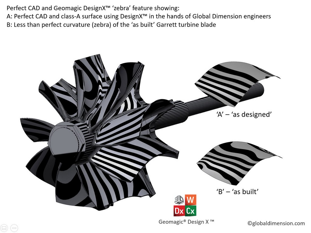
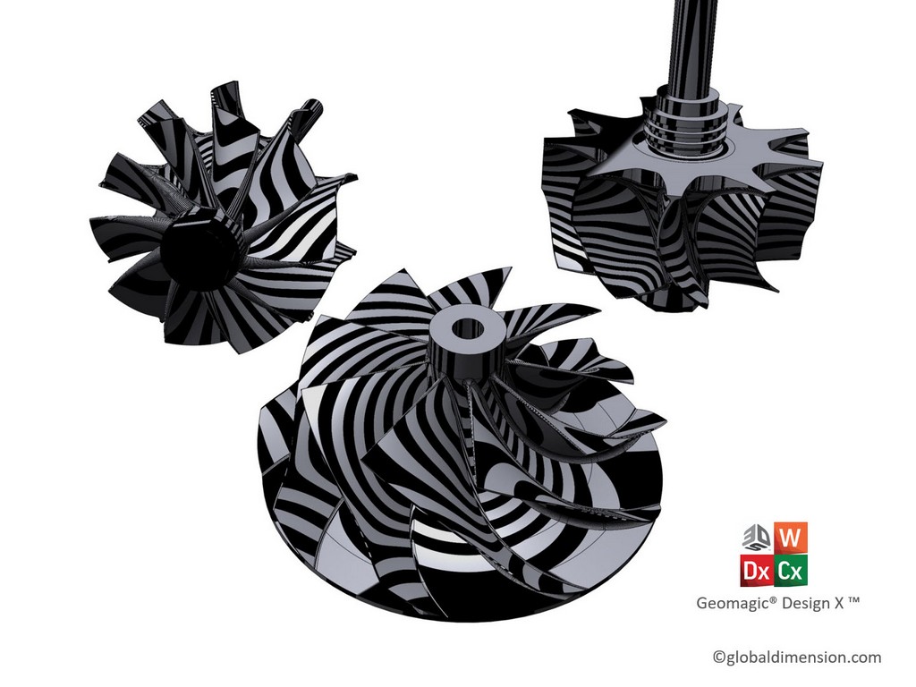
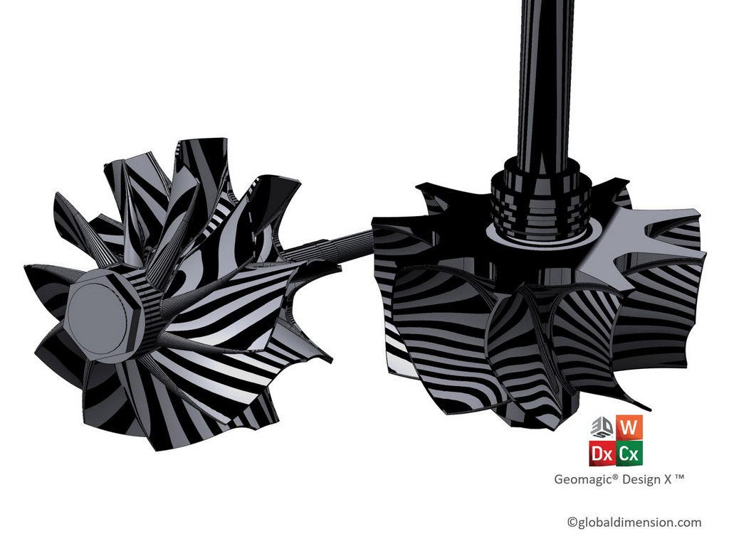
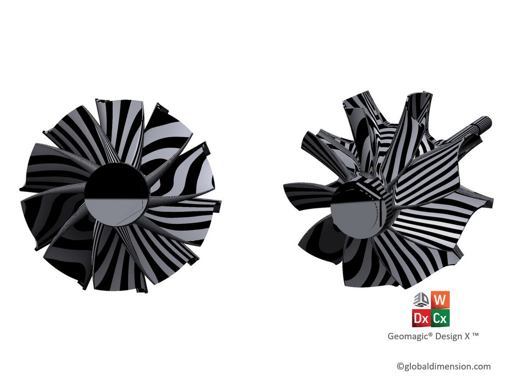
3: Zebra tools
The ‘zebra tool’ in 3D Systems DesignX software is an excellent visualization tool of incorrect curvature. The images with the ‘zebra lines’ are a great way for us to see how smooth and perfect the turbocharger blades are.
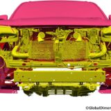
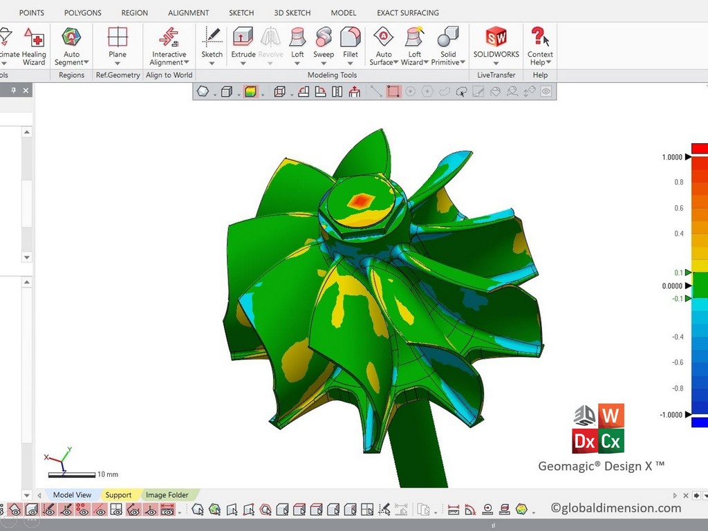
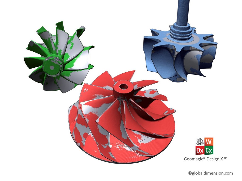
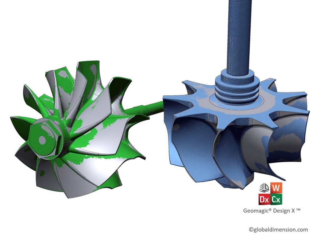
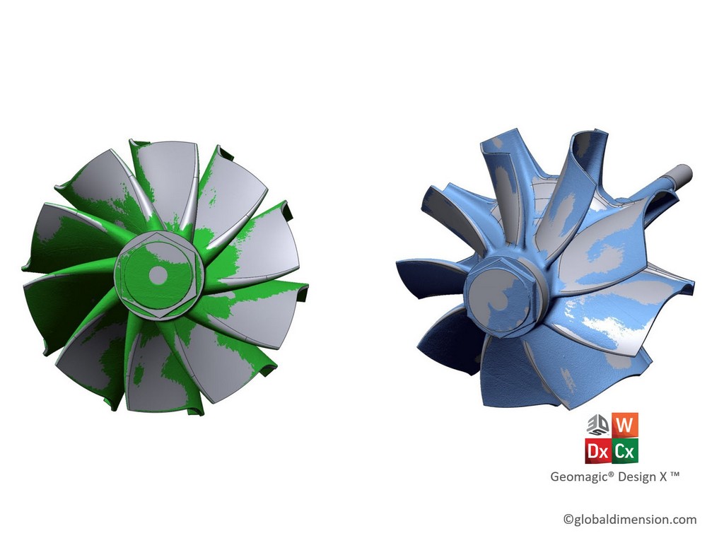
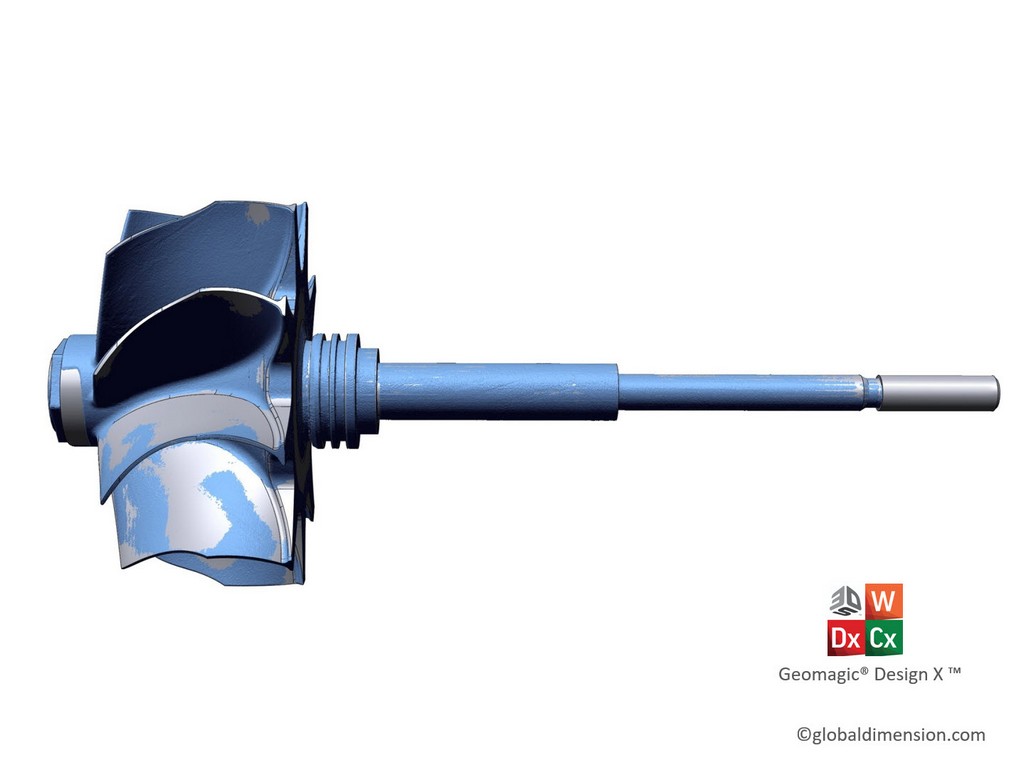
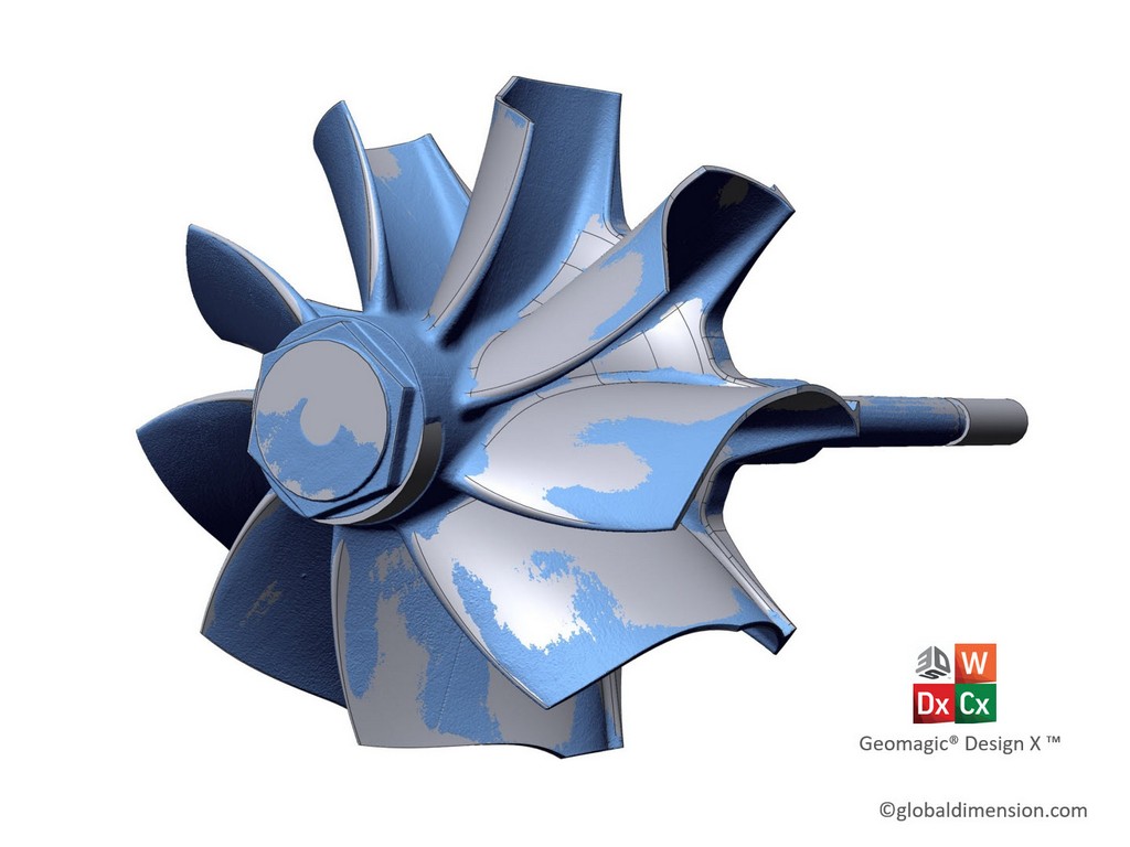
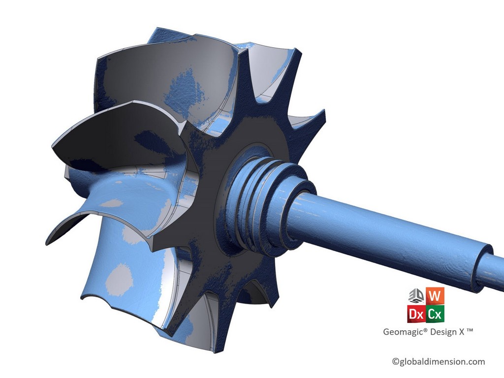
4: 3D compare (scan data vs CAD)
DesignX’s ‘3D compare’ function allows us to see the deviation from the ‘as built’ scan data and our reverse-engineered and refined final CAD data. The bulk of the blades are within +/- 100 micron, with a small amount of casting error showing up in the +/- 200-micron range. Other errors could be in the blades from running the turbocharges to hard/hot and even handling damage. It is best to make the CAD perfect, so when a new mould gets made, we give the new part its best chance at being created with no defects.
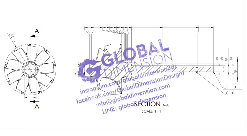
5: SolidWorks for 2D drafting
We also use Solidworks for our 2D drafting needs. We love SolidWorks, Composer and other tools from Dessault Systems.
We love what we do….
At Global Dimension, we scan and reverse thousands of parts every year, and we have become the preeminent scanning service in Thailand. We scan and reverse tiny thing things like watch parts, and we scan huge things like trains and aeroplanes. We scan rocks and trees for artists, and we scan fighter jets. Every day is different. Some of our customers just want scan data, others want full reverse engineering or inspection reports. We have a solution for everyone.
If we can help you with any engineering/CAD/scanning, we will give a special price to anyone into old Harley-Davidsons, Volkswagens, old motorcycles, and other fun things. We feel your passion. We love what you do and will do our best to support you.
Our location is in Downtown Bangkok. Sukhumvit Soi 3, near Bumrungrad Hospital. The BTS is Nana or Ploenchit. We are easy to find at these friendly links:
Facebook: https://www.facebook.com/GlobalDimens…
Instagram: https://www.instagram.com/globaldimen…
Website: https://www.globaldimension.com/blog
Location: https://goo.gl/maps/jWRsCP3fH2K2
LINE: @global_dimension
Phone: +66 (0)2 253 2271
สแกน3มิติ วิศวกรรมย้อนกลับ เครื่องสแกน3มิติ ปริ้น3มิติ ตรวจสอบชิ้นงาน แกะแบบชิ้นงาน เขียนแบบวิศวกรรม สแกนพระ บริการสแกน3มิติ
globaldimension solidworks Geomagic Creaform Faroarm 3dsystems 3ddesign 3dscanning 3dscan reverseengineering vintagebike vwbug vwbeetle aircooledvw vw volkswagen porsche356 garrettturbo turbocharged turbocharger