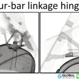
Aermacchi CRTT and Paul Brodie modifications
Paul Brodie (http://flashbackfab.com/) designed and made his own CRTT frame a few years ago, and he was kind enough to share his drawings with me. Paul made his drawing on a very large piece of card stock, as the drawing was full size with wheels.
He sent me the drawing via the mail. Because it was a giant piece of card stock, he cut it up in A3 sized pieces. I scanned each piece and sent it to a Photoshop expert and had them piece it back together. It came out great, coffee stains and all. (SEE PICTURE)
A few years after Paul gave me the drawings, I decided to go another step and scan/reverse engineer my newly acquired CRTT and make precise drawing using CAD software (3D Systems DesignX and SolidWorks).
I was discussing this with Seth Rosko in New York City (http://www.rosko.cc). Seth builds beautiful bicycle frames and races motorcycles. He was also interested in Paul’s hand sketched drawing, so I shared that as well. Seth’s curiosity knows no bounds, and he was interested in knowing what were the primary differences between Paul’s drawing and my CAD drawing. We merged Paul’s handmade drawing and the CAD drawing. For registration of the 2 drawings we used the engine mounts on Paul’s drawing to lineup with the CAD drawing engine mounts.
Key differences are:
– Paul’s frame has a steering angle of 26 degrees.
– CRTT is 51mm shorter wheelbase.
– Pauls’ backbone tube is 54mm longer, and is 3″ OD tube (76mm), 4130 with a .120″ wall thickness. Original is 60mm OD, and Paul used 76mm OD (BIG DIFFERENCE).
– On a CRTT (and almost all Aermacchi) the crankshaft center is on the same horizontal line as the center of the swingarm (bet you didn’t know that!). But in Paul’s drawing, the crankshaft is about 11 mm lower than the swingarm pivot.
– More importantly, the swingarm is moved 18mm further forward, so the drive sprocket is closer to the swingarm pivot (and many say this is a good thing).
– The rails that the seat is attached to are 35mm higher on Paul’s bike, better for a taller rider.
Of course, some of these differences can be a little inaccurate, because we scanned about 15 pieces of cardboard and then Photoshop stitched them together. Not exactly high precision engineering.
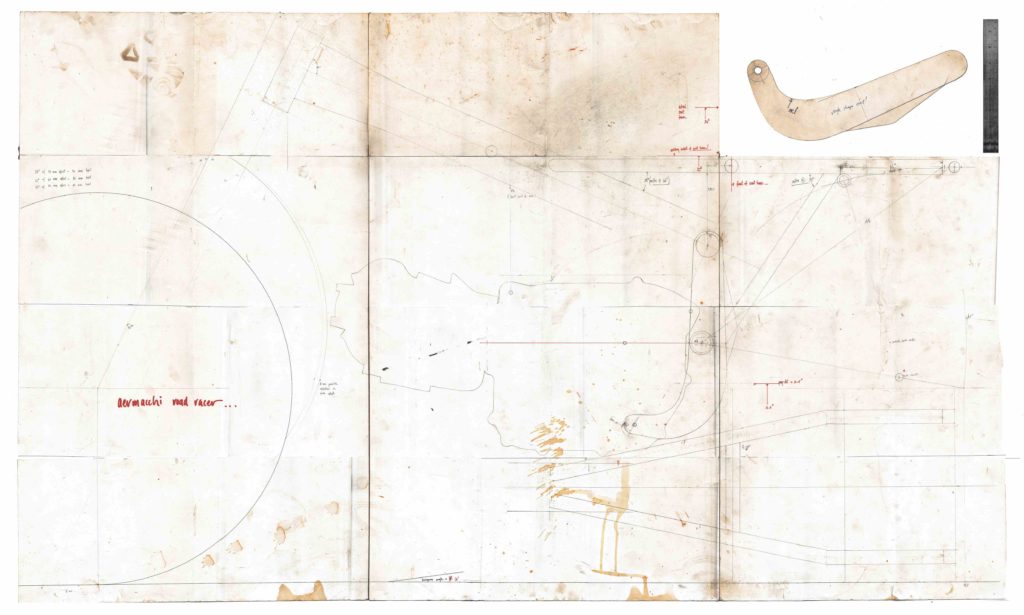
Figure 1: Paul’s hand drawn composite picture drawing of the CRTT frame. Wow.
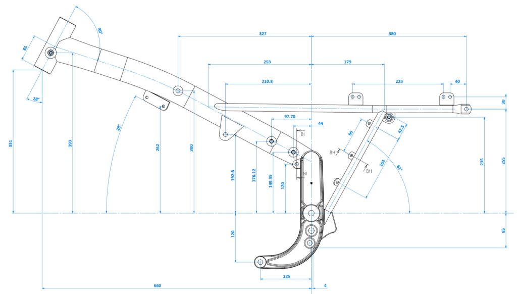
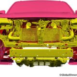
Figure 2: Global Dimension’s CAD of an actual CRTT. Lot of work.
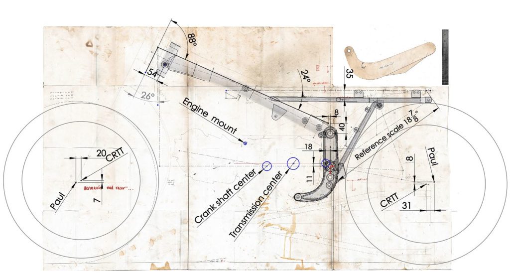
Figure 3: Composite of Paul’s hand drawn CRTT and the CAD drawing of a CRTT.
The forged side plate on the side of the CRTT is 40mm shorter than Paul’s, and at the top of the forging it is 8mm further back. The shape of Paul’s side plate is similar, but different than the CRTT. Take a look at Figure 4.
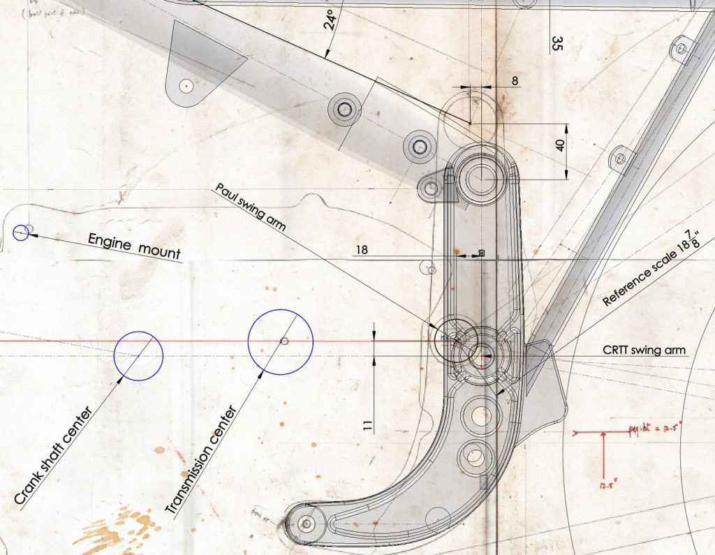
Figure 4: Paul’s paper plans and the CAD drawing zoomed in for critical measurements.
What is the effect of moving the relationships between the locations of the countershaft, swingarm pivot, swingarm lengthening and rear wheel location? There are plenty of great books written about motorcycle frame design that explain this in detail. One of the outcomes of moving these different points around is the change in is anti-squat. I won’t go into the details of anti-squat here, but just provide you with some book references and pictures of the anti-squat data we calculated. Good materials to read are:
- Tony Foale’s has an excerpt of his material here https://www.tonyfoale.com/book/Antisquat.PDF
- Paul Thede’s materials are here https://books.google.co.th/books?id=GWR_H3cMRLoC&pg=PA89
- Andrew Trevitt has a great explanation here: http://www.datamc.org/2016/06/14/anti-squat-geometry/
We can certainly produce a lot of data and confusing pictures, and Figure 5 is one of our most confusing produced by Global Dimension! We are comparing Paul Brodie’s frame and the standard CRTT, for what Paul Thede calls “Instantaneous Force Center (IFC)”. The IFC is used to calculate anti-squat properties of a frame (as per Foale/Thede/Trevitt literature noted above). In the Figure(s) 5/6, Paul Brodie’s data is in red and the standard CRTT data is in blue. We used a front sprocket with 16T and the rear of 38T with a 520 chain, as the sprocket sizes are important in this calculation. Other important data items are the swingarm pivot centers (recall Paul Brodie’s and the CRTT are slightly different) and the rear wheel location. We provide the IFC/Squat-angle data for 4 swingarm locations a) at rest b) 25m compression c) 50mm compression and d) 100mm compression. We plot a curved line for Paul Brodie’s and the CRTT frames, to show the path of the IFC for both frames. Figure 6 shows this data a little more zoomed in and readable, and is a lot more useful than Figure 5.
I put 3 red colored center of gravity (CG) marks in a red box, located on Figure(s) 5/6. We do not know the exact CG of these bikes, so this area is a reasonable guess at where they would be. The CG box is located exactly on the middle of the CRTT, assuming there is a 50/50 weight distribution. CG does move around due to many factors such as how much fuel is on board, rider weight and position.
The big takeaway is the IFC needs to stay away from the CG. But we are not experts on this topic, so there could be even bigger takeaways. Tony Foale is always very helpful in these discussions – he also has seminars on these topics too.
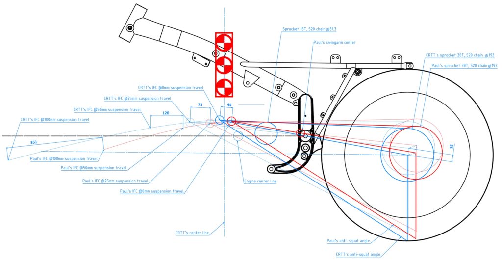
Figure 5: Brodie vs CRTT regarding IFC movement (Brodie = red, CRTT = blue)
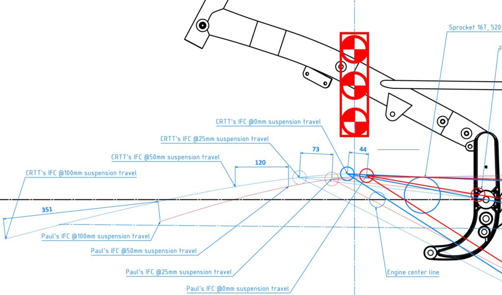
Figure 6: Brodie vs CRTT regarding IFC movement, detail.
I hope you enjoyed seeing how we can merge a paper drawing and a CAD drawing, and examine some of the details of Paul’s work. Please, go to Paul’s site to see real magic in action http://flashbackfab.com/).
For deeper analysis of frames and suspension, please visit :
1) Tony’s site/book at https://www.tonyfoale.com/book.htm
2) Paul Thede’s book at https://www.amazon.com/Techs-Motorcycle-Suspension-Motorbooks-Workshop/dp/0760331405/
3) And Andrew Trevitt’s site: http://www.datamc.org/
More information on Instantaneous Force Center (IFC) and related math can also be found here https://en.wikipedia.org/wiki/Instant_centre_of_rotation.
++++++++++++++++++++++
If we can help you with any engineering/CAD/scanning, we will give a special price to anyone into old Volkswagens, old motorcycles, and other fun things.
We feel your passion. We love what you do and will do our best to support you.
Our location is in Downtown Bangkok. Sukhumvit Soi 3, near Bumrungrad Hospital. The BTS is Nana or Ploenchit. We are easy to find at these friendly links:
Facebook: https://www.facebook.com/GlobalDimensionDesign
Website: www.globaldimension.com
Location: https://goo.gl/maps/jWRsCP3fH2K2
LINE: @global_dimension
Phone: +66 (0)2 253 2271
#3dprinting #3ddesign #3Dscanning#3Dscan #Reverseengineering#globaldimension #Solidworks #catia #3Dsystems #Geomagic #FaroARM #Creaform #cnc #cncowners #globaldimension3d #harleydavidson #vintageharley #americaniron #vintagecar #vintageracing #volkswagen #volkswagenbus #alfaromeo #mvagusta #porsche #porsche356 #drivetastefully #teamobsolete #isleofmantt